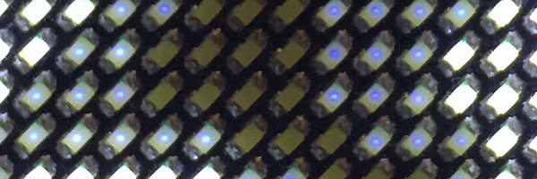
This project is a custom firmware and library for displaying imagery on a small pixel led name badge.
I am interested in using this as a small notification display attached to a computer and have decided to sacrifice the ability to preload a set of messages to scroll in favor of more robust display support. It needs to be tethered to a computer with this firmware.
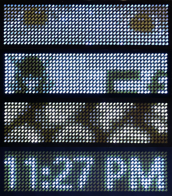
- 4 level gray scale
- 60 Hz frame refresh rate
- 256 levels of brightness in addition to the gray scale (really, a few steps less than that since it has a gamma curve to appear perceptually linear)
- Query button states
- Requesting acknowledgement of commands (setting text on the stock firmware programatically was unreliable)
- Resynchronizing handshake if the command stream is corrupted or overruns
- It can still store a single frame image that will display at start up, even if not tethered
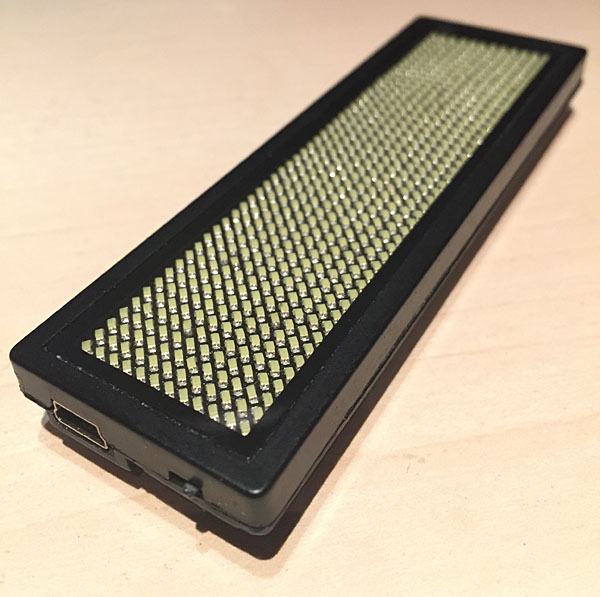
This particular badge is pretty generic and is easy to find under a few different brandings. Different variation in the components and layout exist and a couple are supported by this project.
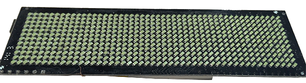
The hardware is identifiable by two buttons on the back (in a horazontal configuration), a mini usb port that is used for data as well as power, and the 48x12 array of SMD leds are packed at a 45 degree angle on the front. I have seen a seller on one popular online retailer even include pictures of the board inside as part of the listing.
Note: I have run across another variant of this 48x12 screen that is totally different inside. I have no idea if it is compatible with this firmware.
48x12 array of leds
Atmel ATMega88PA @12MHz (8 kb program, 1 kb sram, 512 byte internal eeprom)
Prolific PL2303 USB to serial interface
12 MHz crystal oscillator (wired to the ATMega88PA)
2 tact switches
6 74hc595 8-bit shift registers that drive the leds (physically in a 24x24 configuration)
16kb AT24C128C Atmel serial eeprom
ISP header right below the microcontroller
~186 Hz display update rate with this firmware
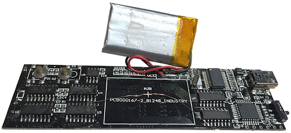
I was lucky and got a nice bodge wire hanging out there.
| Pin | Name | Signal | Component |
|---|---|---|---|
| 1 | PD3 | ||
| 2 | PD4 | ||
| 3 | GND | ||
| 4 | VCC | ||
| 5 | GND | ||
| 6 | VCC | ||
| 7 | PB6 | RES (A) | Oscillator |
| 8 | PB7 | RES (B) | Oscillator |
| 9 | PD5 | ~OE | 74HC595 |
| 10 | PD6 | STCP | 74HC595 |
| 11 | PD7 | DS (A) | 74HC595 |
| 12 | PB0 | SHCP | 74HC595 |
| 13 | PB1 | DS (B) | 74HC595 |
| 14 | PB2 | ||
| 15 | PB3 | MOSI | ISP Header |
| 16 | PB4 | MISO | ISP Header |
| 17 | PB5 | SCK | ISP Header |
| 18 | AVCC | ||
| 19 | ADC6 | ||
| 20 | AREF | ||
| 21 | GND | ||
| 22 | ADC7 | ||
| 23 | PC0 | ||
| 24 | PC1 | ||
| 25 | PC2 | Button 1 | |
| 26 | PC3 | Button 0 | |
| 27 | PC4 | SDA | EEPROM |
| 28 | PC5 | SCL | EEPROM |
| 29 | PC6 | RST | ISP Header |
| 30 | PD0 | TXD | USB Serial |
| 31 | PD1 | RXD | USB Serial |
| 32 | PD2 |
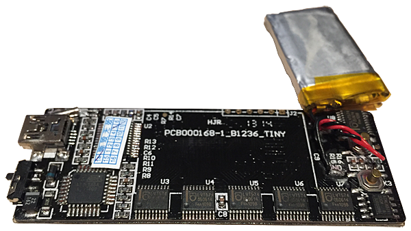
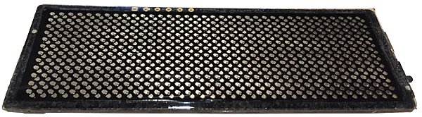
Another supported variant of the badge is slightly smaller (36x12 pixels), the two buttons on the back are in a vertical configuration. The leds are still 45 degrees, but appear to be bonded to the board directly rather than SMD components. It uses a similar (but older) Atmel microcontroller. This variant also uses an older PL2303 as well that requires an external oscillator. Instead of serial shift registers, it uses parallel flip-flops to drive the leds. Because the xtal pins are used up on parallel output (and the usb serial controler is using the crystal anyway), this variant runs at 8 MHz instead of 12 MHz.
36x12 array of leds
Atmel ATMega8A @8MHz (8 kb program, 1 kb sram, 512 byte internal eeprom)
Prolific PL2303 USB to serial interface
12 MHz crystal oscillator (wired to the PL2303)
2 tact switches
6 LT574 8-bit flip-flops that drive the leds (physically in a 36x12 configuration)
16kb AT24C128C Atmel serial eeprom
ISP header right below the battery
~188 Hz display update rate with this firmware
| Pin | Name | Signal | Component |
|---|---|---|---|
| 1 | PD3 | CP (1) | LT574 |
| 2 | PD4 | CP (0) | LT574 |
| 3 | GND | ||
| 4 | VCC | ||
| 5 | GND | ||
| 6 | VCC | ||
| 7 | PB6 | D0 | LT574 |
| 8 | PB7 | D1 | LT574 |
| 9 | PD5 | D2 | LT574 |
| 10 | PD6 | D3 | LT574 |
| 11 | PD7 | D6 | LT574 |
| 12 | PB0 | D5 | LT574 |
| 13 | PB1 | D7 | LT574 |
| 14 | PB2 | D4 | LT574 |
| 15 | PB3 | MOSI + Button 0 | ISP Header |
| 16 | PB4 | MISO | ISP Header |
| 17 | PB5 | SCK + ~OE | ISP Header + LT574 |
| 18 | AVCC | ||
| 19 | ADC6 | ||
| 20 | AREF | ||
| 21 | GND | ||
| 22 | ADC7 | ||
| 23 | PC0 | CP (5) | LT574 |
| 24 | PC1 | CP (4) | LT574 |
| 25 | PC2 | CP (2) | LT574 |
| 26 | PC3 | CP (3) | LT574 |
| 27 | PC4 | SDA | EEPROM |
| 28 | PC5 | SCL | EEPROM |
| 29 | PC6 | RST | ISP Header |
| 30 | PD0 | TXD | USB Serial |
| 31 | PD1 | RXD | USB Serial |
| 32 | PD2 | Button 1 |
Installation of the Prolific PL2303 serial over usb driver is going to be the same as with the stock setup.
I was unfortunate to get a board with a counterfit PL2303 on it and the newer drivers refuse to initialize it - even the version on the disc that came with the badge. I had to roll way back to a Windows Vista version of the driver to get it to work.
You will need an external ISP programmer to update the firmware on the badge. An AVR Dragon works nicely. Be mindful of the ISP header pinout since it may vary between board revisions.
| □ | ○ | ○ | ○ | ○ | ○ |
|---|---|---|---|---|---|
| VCC | GND | RST | SCK | MISO | MOSI |
...