

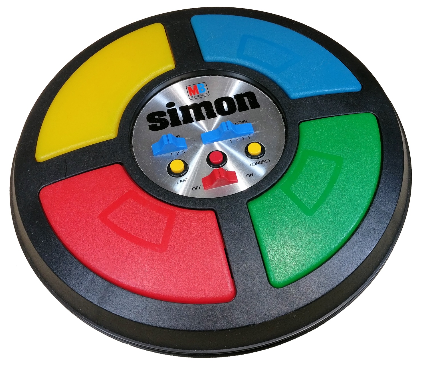
Simon is a memory based game that used to be very popular during the 70s. The player needs to remember the sequence of colours. Each colour is accompanied with its respective tone. The player needs to follow the sequence, and with each round, a new color is added to the sequence. The game ends when the player makes a mistake or times out.
- NXP's LPC2378 (32-bit ARM microcontroller)
- Breadboard
- 4 LEDs (for color display)
- 4 Push buttons (for user input)
- 16x2 LCD Display (for score feedback)
- Wires (duh!)
The core game engine implemented in C. This file handles:
Game State Management: Tracks the current sequence, player progress, score, and high score
Sequence Generation: Uses ADC (Analog-to-Digital Converter) to generate pseudo-random sequences
voidGenerate_Sequence(void) {
for (j=0; j<48; j++) {
read_adc(); // Read analog value from ADCsprintf(cVal, "%f", ((AD_lastcheck / 10.0) * (3.2 / 1023)));
sequence[j] =cVal[7] % 4; // Use last digit mod 4 for randomness
}
}
Why: ADC noise provides entropy for sequence generation; the value is scaled and modulo 4 to get one of four button choices.
LED & Audio Feedback: Each sequence item lights up an LED and plays a unique tone
voidLight_LED(intled_index) {
if (led_index==0) {
FIO0SET=LED1_PIN; // Set GPIO pin highbuzzer(1); // Play tone 1Clear_LEDs();
}
// ... similar for LEDs 2, 3, 4
}
Why: Provides both visual and auditory cues to the player, mimicking the original Simon game.
Input Validation: Checks if player button presses match the sequence
intCheck_Player_Input(intled_index) {
Light_LED(button_press);
if (sequence[player_index] ==led_index) {
player_index++;
if (player_index==sequence_length) {
player_index=0;
return1; // Round complete, advance to next round
}
} else {
return-1; // Player failed
}
}
Why: Core game mechanic: validates user input and handles win/loss conditions.
Timeout Mechanism: 4-second timer for player response; times out after no input
voidenable_timer(void) {
T0PR=1;
T0MR0=1200-1; // Match register for timer intervalT0MCR=3; // Interrupt and reset on matchT0TCR=1; // Start timerwhile (count3<4000) {
if (T0IR& (1 << 0)) {
T0IR= (1 << 0); // Clear interrupt flagcount3++;
}
if (button_press!=-1) break; // Player responded
}
}
Why: Enforces a time limit for player input, adding difficulty to the game.
Manages 16x2 character LCD in 4-bit mode (uses only 4 data pins for reduced wiring):
Pin Configuration: Uses P1.24-P1.27 for data, P1.28-P1.31 for control lines
#definePIN_E 0x80000000 // Enable (strobe)
#definePIN_RW 0x20000000 // Read/Write
#definePIN_RS 0x10000000 // Register Select
Busy Waiting: Checks LCD busy flag before writing data
staticunsigned charwait_while_busy (void) {
do {
status=lcd_read_status();
} while (status&0x80); // Busy flag is bit 7return (status);
}
Why: Ensures LCD is ready for the next command; prevents data corruption.
4-bit Data Writing: Sends each byte in two 4-bit nibbles
voidlcd_write_cmd (unsigned charc) {
wait_while_busy();
LCD_RS(0);
lcd_write_4bit (c>>4); // Send upper 4 bitslcd_write_4bit (c); // Send lower 4 bits
}
Why: 4-bit mode reduces GPIO pins required from 8 to 4 (plus 3 control lines).
Display Output: Prints game state (current score, high score, messages)
sprintf(highscore_msg, " CS: %d HS: %d", score, highscore);
set_cursor(0, 0);
lcd_print(highscore_msg);
Low-level GPIO control for LEDs:
Initialization: Configures P2.0-P2.7 as outputs
voidLED_Init(void) {
PINSEL10=0; // Disable ETM, enable GPIOFIO2DIR=0x000000FF; // P2.0..7 as outputsFIO2MASK=0x00000000;
}
LED Operations:
LED_On(num): Turns on LED at pinnumviaFIO2SET(set bits)LED_Off(num): Turns off LED at pinnumviaFIO2CLR(clear bits)LED_Out(value): Sets all 8 LEDs based on a byte value
Reads analog input for randomness and button state detection:
ADC Initialization:
voidinit_adc() {
PCONP |= (1 << 12) | (1 << 1) | (1 << 22) | (1 << 2); // Enable ADC, DAC blocksPINSEL1=0x254000; // Configure pin functionsDACR=0x0; // DAC initial output
}
Reading ADC:
voidread_adc() {
AD0CR=0x00200004; // Select ADC channel 2AD0CR |= (1 << 24); // Start conversionfor (i=0; i<99999; i++); // Wait for conversionAD_lastcheck= (AD0DR2 >> 6) &0x3FF; // Read 10-bit result
}
Where: Channel 2 of ADC block 0 (pin 0.25)
Why: Provides entropy source for random sequence generation.
Event-driven button input using external interrupts:
- Button Press Handlers: External interrupts EINT0-EINT3 map to the 4 buttons
Why: Interrupt-driven approach is more responsive than polling; frees CPU for other tasks.
__irqvoideint0_irq(void) {
button_press=0; // Record button 0 pressedEXTINT=0x01; // Clear interrupt flagVICVectAddr=0; // Acknowledge to VIC
}
ARM assembly startup routine that:
Initializes CPU Clocks: Sets up PLL to 72 MHz from 12 MHz oscillator
; Configure PLL multiply (M=12) and divide (N=1); CCLK = (2 * M * Fosc) / N = (2 * 12 * 12MHz) / 1 = 72MHzLDR R3, =PLLCFG_Val ; PLLCFG = 0x0000000B (M-1=11, N-1=0)STR R3,[R0, #PLLCFG_OFS]
Sets Up Stack Pointers: Different stacks for each CPU mode (User, IRQ, FIQ, etc.)
LDR R0, =Stack_TopMSR CPSR_c, #Mode_IRQ:OR:I_Bit:OR:F_BitMOVSP, R0SUB R0, R0, #IRQ_Stack_Size ; Decrement for next mode
Copies Interrupt Vectors to RAM (if RAM_INTVEC defined)
Jumps to Main C Code: Calls
main()after hardware initialization
- Initialization: Setup GPIO, ADC, LCD, interrupts, timers
- Generate Sequence: Create 48-item random sequence using ADC noise
- Game Loop:
- Display current score & high score on LCD
- Play sequence to player with LEDs & audio
- Wait for player to match sequence (4-second timeout per input)
- Validate each button press
- If all buttons in sequence pressed correctly → advance to next round
- If mistake or timeout → game over; show final score
- Restart: Return to step 1 for a new game
- Toolchain: Keil MDK (ARM C/C++ Compiler)
- Target: LPC2378 ARM7 (48 MHz default, PLL configurable to 72 MHz)
- Memory: 512 KB Flash, 64 KB SRAM
README generated by Copilot[Claude Haiku 4.5]! (few manual edits though)