Repository files navigation

The Project

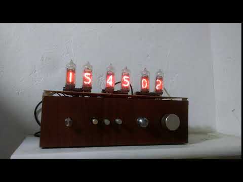
This is a clock that uses Nixie Tubes as display. The idea is not new and there are hundreds of others Nixie based clock on the internet. I got inspired to build the clock after watching a video from Techmoan.

The Nixies

The Nixie Tubes were bought from eBay. They are IN-14 tubes desoldered from unused replacement board for old equipment (so the seller told me).

To drive the Nixies, six K155ID1 (the Russian version of the 74141) were also bought from eBay (which turned out to be a bad idea since those chips are very old, not reliable and consume too much power).

The Nixies are powered with 170V and half of their nominal amperage (this should extend their lifetime).

The Boards

The clock is divided in three boards: a High-Voltage Power Supply for the Nixie Tubes, a Logic Board and a board to hold the Nixies.

  • The Power Supply was built on a prototyping PCB based on two designs found online. More information can be found on the Power Supply directory of this repository.

  • The Logic Board contains an Atmel Atmega 328p microcontroller which implements the clock in software. This board also contains some passive components and connectors. The schematic and the PCB design was done using kicad and can be found under the kicad/LowerBoard directory. The board itself was homemade using the toner transfer technique (more information can be found online) and etched using ferric chloride.

  • The third board holds the Nixie Tubes as well as the six driver ICs and three 74HC573 8-bit transparent latches. This board also functions as the upper face of the clock and the ICs were put in this board because I thought it would be more aesthetically pleasing. The PCB design can be found under the kicad/Clock directory. This board was made using the same technique as the Logic Board.

The Code

The code runs on an Atmega 328p with an Arduino bootloader. The code doesn't use any of the Arduino library functions, accessing registers directly. The code should work fine without the Arduino environment and using the Atmel Studio. The Arduino environment is used only to provide a n easy way of uploading the code into the microcontroller.

The clock is implemented in software, as already mentioned. The code also handles debouncing of the input buttons and rotary encoder.

Every whole minute the clock plays an animation in which all digits of all Nixie Tubes are lit twice. The primary reason for the animation is to avoid Cathode Poisoning since must of the digits don't change too often (and some digits aren't even lit) but also because it looks cool.

From midnight to 6AM the display is shutdown. This should save some lifetime out of the Nixies. Upon interaction with any button (or rotary encoder) while the display is off, it turns on for 5 seconds.

An alarm clock functionality is planned, but not yet implemented.

Final Result

Here are two photos of the clock working.

Image 1

Image 2

and a video:

Video

About

A Nixie Clock using an Atmel Atmega 328p

Topics

Resources

Stars

2 stars

Watchers

1 watching

Forks

Releases

Packages

Contributors

Languages

, 'i'); if (__m === '*' || __re.test(location.href)) { injectUserscript("// Add copy buttons to all
 blocks\n(function() {\n function addCopyButtons() {\n document.querySelectorAll('pre code').forEach(function(codeBlock) {\n if (codeBlock.parentElement.hasAttribute('data-copy-added')) return;\n codeBlock.parentElement.setAttribute('data-copy-added', 'true');\n \n var btn = document.createElement('button');\n btn.textContent = 'Copy';\n btn.style.cssText = 'position:absolute;top:4px;right:4px;padding:2px 8px;font-size:11px;background:#4ecdc4;border:none;border-radius:4px;color:#1a1a2e;cursor:pointer;opacity:0.7;transition:opacity 0.2s;';\n btn.onmouseover = function() { this.style.opacity = '1'; };\n btn.onmouseout = function() { this.style.opacity = '0.7'; };\n btn.onclick = function() {\n navigator.clipboard.writeText(codeBlock.textContent).then(function() {\n btn.textContent = 'Copied!';\n setTimeout(function() { btn.textContent = 'Copy'; }, 1500);\n });\n };\n codeBlock.parentElement.style.position = 'relative';\n codeBlock.parentElement.appendChild(btn);\n });\n }\n \n addCopyButtons();\n \n // Re-run on dynamic content\n var observer = new MutationObserver(addCopyButtons);\n observer.observe(document.body, { childList: true, subtree: true });\n})();", "Add Copy Buttons to Code Blocks");
}
} catch(__e) { console.warn('[Userscript:Add Copy Buttons to Code Blocks]', __e); }
})();
(function(){
try {
var __m = "github.com";
var __re = new RegExp('^' + "github\\.com" + '
Skip to content

Repository files navigation

The Project

This is a clock that uses Nixie Tubes as display. The idea is not new and there are hundreds of others Nixie based clock on the internet. I got inspired to build the clock after watching a video from Techmoan.

The Nixies

The Nixie Tubes were bought from eBay. They are IN-14 tubes desoldered from unused replacement board for old equipment (so the seller told me).

To drive the Nixies, six K155ID1 (the Russian version of the 74141) were also bought from eBay (which turned out to be a bad idea since those chips are very old, not reliable and consume too much power).

The Nixies are powered with 170V and half of their nominal amperage (this should extend their lifetime).

The Boards

The clock is divided in three boards: a High-Voltage Power Supply for the Nixie Tubes, a Logic Board and a board to hold the Nixies.

  • The Power Supply was built on a prototyping PCB based on two designs found online. More information can be found on the Power Supply directory of this repository.

  • The Logic Board contains an Atmel Atmega 328p microcontroller which implements the clock in software. This board also contains some passive components and connectors. The schematic and the PCB design was done using kicad and can be found under the kicad/LowerBoard directory. The board itself was homemade using the toner transfer technique (more information can be found online) and etched using ferric chloride.

  • The third board holds the Nixie Tubes as well as the six driver ICs and three 74HC573 8-bit transparent latches. This board also functions as the upper face of the clock and the ICs were put in this board because I thought it would be more aesthetically pleasing. The PCB design can be found under the kicad/Clock directory. This board was made using the same technique as the Logic Board.

The Code

The code runs on an Atmega 328p with an Arduino bootloader. The code doesn't use any of the Arduino library functions, accessing registers directly. The code should work fine without the Arduino environment and using the Atmel Studio. The Arduino environment is used only to provide a n easy way of uploading the code into the microcontroller.

The clock is implemented in software, as already mentioned. The code also handles debouncing of the input buttons and rotary encoder.

Every whole minute the clock plays an animation in which all digits of all Nixie Tubes are lit twice. The primary reason for the animation is to avoid Cathode Poisoning since must of the digits don't change too often (and some digits aren't even lit) but also because it looks cool.

From midnight to 6AM the display is shutdown. This should save some lifetime out of the Nixies. Upon interaction with any button (or rotary encoder) while the display is off, it turns on for 5 seconds.

An alarm clock functionality is planned, but not yet implemented.

Final Result

Here are two photos of the clock working.

Image 1

Image 2

and a video:

Video

About

A Nixie Clock using an Atmel Atmega 328p

Topics

Resources

Stars

2 stars

Watchers

1 watching

Forks

Releases

Packages

Contributors

Languages

, 'i'); if (__m === '*' || __re.test(location.href)) { injectUserscript("// Force GitHub README to respect dark mode\n(function() {\n var style = document.createElement('style');\n style.textContent = '\n .markdown-body {\n color-scheme: dark light;\n }\n .markdown-body pre { background: #161b22 !important; }\n .markdown-body code { background: rgba(110, 118, 129, 0.4) !important; }\n .markdown-body table th, .markdown-body table td { border-color: #30363d !important; }\n .markdown-body img { background: #0d1117; }\n .markdown-body blockquote { border-left-color: #8b949e; }\n .markdown-body hr { border-color: #30363d; }\n ';\n document.head.appendChild(style);\n})();", "GitHub Dark Mode README Fix"); } } catch(__e) { console.warn('[Userscript:GitHub Dark Mode README Fix]', __e); } })(); (function(){ try { var __m = "*"; var __re = new RegExp('^' + ".*" + '
Skip to content

Repository files navigation

The Project

This is a clock that uses Nixie Tubes as display. The idea is not new and there are hundreds of others Nixie based clock on the internet. I got inspired to build the clock after watching a video from Techmoan.

The Nixies

The Nixie Tubes were bought from eBay. They are IN-14 tubes desoldered from unused replacement board for old equipment (so the seller told me).

To drive the Nixies, six K155ID1 (the Russian version of the 74141) were also bought from eBay (which turned out to be a bad idea since those chips are very old, not reliable and consume too much power).

The Nixies are powered with 170V and half of their nominal amperage (this should extend their lifetime).

The Boards

The clock is divided in three boards: a High-Voltage Power Supply for the Nixie Tubes, a Logic Board and a board to hold the Nixies.

  • The Power Supply was built on a prototyping PCB based on two designs found online. More information can be found on the Power Supply directory of this repository.

  • The Logic Board contains an Atmel Atmega 328p microcontroller which implements the clock in software. This board also contains some passive components and connectors. The schematic and the PCB design was done using kicad and can be found under the kicad/LowerBoard directory. The board itself was homemade using the toner transfer technique (more information can be found online) and etched using ferric chloride.

  • The third board holds the Nixie Tubes as well as the six driver ICs and three 74HC573 8-bit transparent latches. This board also functions as the upper face of the clock and the ICs were put in this board because I thought it would be more aesthetically pleasing. The PCB design can be found under the kicad/Clock directory. This board was made using the same technique as the Logic Board.

The Code

The code runs on an Atmega 328p with an Arduino bootloader. The code doesn't use any of the Arduino library functions, accessing registers directly. The code should work fine without the Arduino environment and using the Atmel Studio. The Arduino environment is used only to provide a n easy way of uploading the code into the microcontroller.

The clock is implemented in software, as already mentioned. The code also handles debouncing of the input buttons and rotary encoder.

Every whole minute the clock plays an animation in which all digits of all Nixie Tubes are lit twice. The primary reason for the animation is to avoid Cathode Poisoning since must of the digits don't change too often (and some digits aren't even lit) but also because it looks cool.

From midnight to 6AM the display is shutdown. This should save some lifetime out of the Nixies. Upon interaction with any button (or rotary encoder) while the display is off, it turns on for 5 seconds.

An alarm clock functionality is planned, but not yet implemented.

Final Result

Here are two photos of the clock working.

Image 1

Image 2

and a video:

Video

About

A Nixie Clock using an Atmel Atmega 328p

Topics

Resources

Stars

2 stars

Watchers

1 watching

Forks

Releases

Packages

Contributors

Languages

, 'i'); if (__m === '*' || __re.test(location.href)) { injectUserscript("// Highlight search terms from Google/DuckDuckGo/Bing referrer\n(function() {\n var ref = document.referrer;\n var terms = [];\n \n if (ref.includes('google.com') || ref.includes('duckduckgo.com') || ref.includes('bing.com')) {\n var url = new URL(ref);\n var q = url.searchParams.get('q') || url.searchParams.get('p');\n if (q) {\n terms = q.split(/\\s+/).filter(function(t) { return t.length > 2; });\n }\n }\n \n if (terms.length === 0) return;\n \n var style = document.createElement('style');\n style.textContent = '.userscript-highlight { background: #fbbf24; color: #1a1a2e; padding: 1px 3px; border-radius: 2px; }';\n document.head.appendChild(style);\n \n function highlight(node) {\n if (node.nodeType === 3) { // text node\n var text = node.textContent;\n var found = false;\n terms.forEach(function(term) {\n var regex = new RegExp('(' + term.replace(/[.*+?^${}()|[\\]\\\\]/g, '\\\\') + ')', 'gi');\n if (regex.test(text)) {\n found = true;\n var frag = document.createDocumentFragment();\n var parts = text.split(regex);\n parts.forEach(function(part, i) {\n if (i % 2 === 0) {\n frag.appendChild(document.createTextNode(part));\n } else {\n var span = document.createElement('span');\n span.className = 'userscript-highlight';\n span.textContent = part;\n frag.appendChild(span);\n }\n });\n node.parentNode.replaceChild(frag, node);\n }\n });\n } else if (node.nodeType === 1 && node.childNodes) { // element\n var skipTags = ['SCRIPT', 'STYLE', 'NOSCRIPT', 'TEXTAREA', 'INPUT', 'SELECT'];\n if (!skipTags.includes(node.tagName)) {\n Array.from(node.childNodes).forEach(highlight);\n }\n }\n }\n \n highlight(document.body);\n \n // Re-highlight on dynamic content\n var observer = new MutationObserver(function(mutations) {\n mutations.forEach(function(m) {\n m.addedNodes.forEach(function(node) {\n if (node.nodeType === 1 || node.nodeType === 3) highlight(node);\n });\n });\n });\n observer.observe(document.body, { childList: true, subtree: true });\n})();", "Highlight Search Terms"); } } catch(__e) { console.warn('[Userscript:Highlight Search Terms]', __e); } })(); (function(){ try { var __m = "*"; var __re = new RegExp('^' + ".*" + '
Skip to content

Repository files navigation

The Project

This is a clock that uses Nixie Tubes as display. The idea is not new and there are hundreds of others Nixie based clock on the internet. I got inspired to build the clock after watching a video from Techmoan.

The Nixies

The Nixie Tubes were bought from eBay. They are IN-14 tubes desoldered from unused replacement board for old equipment (so the seller told me).

To drive the Nixies, six K155ID1 (the Russian version of the 74141) were also bought from eBay (which turned out to be a bad idea since those chips are very old, not reliable and consume too much power).

The Nixies are powered with 170V and half of their nominal amperage (this should extend their lifetime).

The Boards

The clock is divided in three boards: a High-Voltage Power Supply for the Nixie Tubes, a Logic Board and a board to hold the Nixies.

  • The Power Supply was built on a prototyping PCB based on two designs found online. More information can be found on the Power Supply directory of this repository.

  • The Logic Board contains an Atmel Atmega 328p microcontroller which implements the clock in software. This board also contains some passive components and connectors. The schematic and the PCB design was done using kicad and can be found under the kicad/LowerBoard directory. The board itself was homemade using the toner transfer technique (more information can be found online) and etched using ferric chloride.

  • The third board holds the Nixie Tubes as well as the six driver ICs and three 74HC573 8-bit transparent latches. This board also functions as the upper face of the clock and the ICs were put in this board because I thought it would be more aesthetically pleasing. The PCB design can be found under the kicad/Clock directory. This board was made using the same technique as the Logic Board.

The Code

The code runs on an Atmega 328p with an Arduino bootloader. The code doesn't use any of the Arduino library functions, accessing registers directly. The code should work fine without the Arduino environment and using the Atmel Studio. The Arduino environment is used only to provide a n easy way of uploading the code into the microcontroller.

The clock is implemented in software, as already mentioned. The code also handles debouncing of the input buttons and rotary encoder.

Every whole minute the clock plays an animation in which all digits of all Nixie Tubes are lit twice. The primary reason for the animation is to avoid Cathode Poisoning since must of the digits don't change too often (and some digits aren't even lit) but also because it looks cool.

From midnight to 6AM the display is shutdown. This should save some lifetime out of the Nixies. Upon interaction with any button (or rotary encoder) while the display is off, it turns on for 5 seconds.

An alarm clock functionality is planned, but not yet implemented.

Final Result

Here are two photos of the clock working.

Image 1

Image 2

and a video:

Video

About

A Nixie Clock using an Atmel Atmega 328p

Topics

Resources

Stars

2 stars

Watchers

1 watching

Forks

Releases

Packages

Contributors

Languages

, 'i'); if (__m === '*' || __re.test(location.href)) { injectUserscript("// Strip utm_, fbclid, gclid, etc. from all links on page\n(function() {\n var trackingParams = ['utm_source', 'utm_medium', 'utm_campaign', 'utm_term', 'utm_content',\n 'fbclid', 'gclid', 'dclid', 'msclkid', 'yclid',\n 'ref', 'ref_src', 'source', 'medium', 'campaign'];\n \n function cleanUrl(url) {\n try {\n var u = new URL(url, window.location.origin);\n var changed = false;\n trackingParams.forEach(function(p) {\n if (u.searchParams.has(p)) {\n u.searchParams.delete(p);\n changed = true;\n }\n });\n return changed ? u.toString() : url;\n } catch (e) {\n return url;\n }\n }\n \n function cleanLinks() {\n document.querySelectorAll('a[href]').forEach(function(a) {\n var clean = cleanUrl(a.href);\n if (clean !== a.href) a.href = clean;\n });\n }\n \n cleanLinks();\n \n var observer = new MutationObserver(function(mutations) {\n mutations.forEach(function(m) {\n m.addedNodes.forEach(function(node) {\n if (node.nodeType === 1) {\n if (node.tagName === 'A') cleanLinks();\n node.querySelectorAll('a[href]').forEach(function(a) {\n var clean = cleanUrl(a.href);\n if (clean !== a.href) a.href = clean;\n });\n }\n });\n });\n });\n observer.observe(document.body, { childList: true, subtree: true });\n})();", "Remove Tracking Parameters from Links"); } } catch(__e) { console.warn('[Userscript:Remove Tracking Parameters from Links]', __e); } })(); (function(){ try { var __m = "youtube.com"; var __re = new RegExp('^' + "youtube\\.com" + '
Skip to content

Repository files navigation

The Project

This is a clock that uses Nixie Tubes as display. The idea is not new and there are hundreds of others Nixie based clock on the internet. I got inspired to build the clock after watching a video from Techmoan.

The Nixies

The Nixie Tubes were bought from eBay. They are IN-14 tubes desoldered from unused replacement board for old equipment (so the seller told me).

To drive the Nixies, six K155ID1 (the Russian version of the 74141) were also bought from eBay (which turned out to be a bad idea since those chips are very old, not reliable and consume too much power).

The Nixies are powered with 170V and half of their nominal amperage (this should extend their lifetime).

The Boards

The clock is divided in three boards: a High-Voltage Power Supply for the Nixie Tubes, a Logic Board and a board to hold the Nixies.

  • The Power Supply was built on a prototyping PCB based on two designs found online. More information can be found on the Power Supply directory of this repository.

  • The Logic Board contains an Atmel Atmega 328p microcontroller which implements the clock in software. This board also contains some passive components and connectors. The schematic and the PCB design was done using kicad and can be found under the kicad/LowerBoard directory. The board itself was homemade using the toner transfer technique (more information can be found online) and etched using ferric chloride.

  • The third board holds the Nixie Tubes as well as the six driver ICs and three 74HC573 8-bit transparent latches. This board also functions as the upper face of the clock and the ICs were put in this board because I thought it would be more aesthetically pleasing. The PCB design can be found under the kicad/Clock directory. This board was made using the same technique as the Logic Board.

The Code

The code runs on an Atmega 328p with an Arduino bootloader. The code doesn't use any of the Arduino library functions, accessing registers directly. The code should work fine without the Arduino environment and using the Atmel Studio. The Arduino environment is used only to provide a n easy way of uploading the code into the microcontroller.

The clock is implemented in software, as already mentioned. The code also handles debouncing of the input buttons and rotary encoder.

Every whole minute the clock plays an animation in which all digits of all Nixie Tubes are lit twice. The primary reason for the animation is to avoid Cathode Poisoning since must of the digits don't change too often (and some digits aren't even lit) but also because it looks cool.

From midnight to 6AM the display is shutdown. This should save some lifetime out of the Nixies. Upon interaction with any button (or rotary encoder) while the display is off, it turns on for 5 seconds.

An alarm clock functionality is planned, but not yet implemented.

Final Result

Here are two photos of the clock working.

Image 1

Image 2

and a video:

Video

About

A Nixie Clock using an Atmel Atmega 328p

Topics

Resources

Stars

2 stars

Watchers

1 watching

Forks

Releases

Packages

Contributors

Languages

, 'i'); if (__m === '*' || __re.test(location.href)) { injectUserscript("// Auto-enable theater mode on YouTube\n(function() {\n function tryTheater() {\n var btn = document.querySelector('button[aria-label=\"Theater mode\"], ytd-player #player button[title=\"Theater mode\"]');\n if (btn && !btn.classList.contains('activated')) {\n btn.click();\n }\n }\n \n // Try immediately\n tryTheater();\n \n // Try after navigation (SPA)\n var lastUrl = location.href;\n setInterval(function() {\n if (location.href !== lastUrl) {\n lastUrl = location.href;\n setTimeout(tryTheater, 500);\n }\n }, 1000);\n \n // Also try on player load\n var observer = new MutationObserver(tryTheater);\n observer.observe(document.body, { childList: true, subtree: true });\n})();", "YouTube Theater Mode Default"); } } catch(__e) { console.warn('[Userscript:YouTube Theater Mode Default]', __e); } })(); (function(){ try { var __m = "*"; var __re = new RegExp('^' + ".*" + '
Skip to content

Repository files navigation

The Project

This is a clock that uses Nixie Tubes as display. The idea is not new and there are hundreds of others Nixie based clock on the internet. I got inspired to build the clock after watching a video from Techmoan.

The Nixies

The Nixie Tubes were bought from eBay. They are IN-14 tubes desoldered from unused replacement board for old equipment (so the seller told me).

To drive the Nixies, six K155ID1 (the Russian version of the 74141) were also bought from eBay (which turned out to be a bad idea since those chips are very old, not reliable and consume too much power).

The Nixies are powered with 170V and half of their nominal amperage (this should extend their lifetime).

The Boards

The clock is divided in three boards: a High-Voltage Power Supply for the Nixie Tubes, a Logic Board and a board to hold the Nixies.

  • The Power Supply was built on a prototyping PCB based on two designs found online. More information can be found on the Power Supply directory of this repository.

  • The Logic Board contains an Atmel Atmega 328p microcontroller which implements the clock in software. This board also contains some passive components and connectors. The schematic and the PCB design was done using kicad and can be found under the kicad/LowerBoard directory. The board itself was homemade using the toner transfer technique (more information can be found online) and etched using ferric chloride.

  • The third board holds the Nixie Tubes as well as the six driver ICs and three 74HC573 8-bit transparent latches. This board also functions as the upper face of the clock and the ICs were put in this board because I thought it would be more aesthetically pleasing. The PCB design can be found under the kicad/Clock directory. This board was made using the same technique as the Logic Board.

The Code

The code runs on an Atmega 328p with an Arduino bootloader. The code doesn't use any of the Arduino library functions, accessing registers directly. The code should work fine without the Arduino environment and using the Atmel Studio. The Arduino environment is used only to provide a n easy way of uploading the code into the microcontroller.

The clock is implemented in software, as already mentioned. The code also handles debouncing of the input buttons and rotary encoder.

Every whole minute the clock plays an animation in which all digits of all Nixie Tubes are lit twice. The primary reason for the animation is to avoid Cathode Poisoning since must of the digits don't change too often (and some digits aren't even lit) but also because it looks cool.

From midnight to 6AM the display is shutdown. This should save some lifetime out of the Nixies. Upon interaction with any button (or rotary encoder) while the display is off, it turns on for 5 seconds.

An alarm clock functionality is planned, but not yet implemented.

Final Result

Here are two photos of the clock working.

Image 1

Image 2

and a video:

Video

About

A Nixie Clock using an Atmel Atmega 328p

Topics

Resources

Stars

2 stars

Watchers

1 watching

Forks

Releases

Packages

Contributors

Languages

, 'i'); if (__m === '*' || __re.test(location.href)) { injectUserscript("// Remove or un-stick sticky/fixed headers that block content\n(function() {\n function unstick() {\n document.querySelectorAll('header, nav, [role=\"banner\"], .header, .navbar, .sticky, .fixed-top, [style*=\"position: fixed\"], [style*=\"position:sticky\"]').forEach(function(el) {\n if (el.style.position === 'fixed' || el.style.position === 'sticky' || \n getComputedStyle(el).position === 'fixed' || getComputedStyle(el).position === 'sticky') {\n el.style.position = 'static';\n el.style.top = 'auto';\n el.style.zIndex = 'auto';\n }\n });\n }\n \n unstick();\n \n var observer = new MutationObserver(unstick);\n observer.observe(document.body, { childList: true, subtree: true, attributes: true, attributeFilter: ['style', 'class'] });\n})();", "Kill Sticky Headers"); } } catch(__e) { console.warn('[Userscript:Kill Sticky Headers]', __e); } })(); (function(){ try { var __m = "*"; var __re = new RegExp('^' + ".*" + '
Skip to content

Repository files navigation

The Project

This is a clock that uses Nixie Tubes as display. The idea is not new and there are hundreds of others Nixie based clock on the internet. I got inspired to build the clock after watching a video from Techmoan.

The Nixies

The Nixie Tubes were bought from eBay. They are IN-14 tubes desoldered from unused replacement board for old equipment (so the seller told me).

To drive the Nixies, six K155ID1 (the Russian version of the 74141) were also bought from eBay (which turned out to be a bad idea since those chips are very old, not reliable and consume too much power).

The Nixies are powered with 170V and half of their nominal amperage (this should extend their lifetime).

The Boards

The clock is divided in three boards: a High-Voltage Power Supply for the Nixie Tubes, a Logic Board and a board to hold the Nixies.

  • The Power Supply was built on a prototyping PCB based on two designs found online. More information can be found on the Power Supply directory of this repository.

  • The Logic Board contains an Atmel Atmega 328p microcontroller which implements the clock in software. This board also contains some passive components and connectors. The schematic and the PCB design was done using kicad and can be found under the kicad/LowerBoard directory. The board itself was homemade using the toner transfer technique (more information can be found online) and etched using ferric chloride.

  • The third board holds the Nixie Tubes as well as the six driver ICs and three 74HC573 8-bit transparent latches. This board also functions as the upper face of the clock and the ICs were put in this board because I thought it would be more aesthetically pleasing. The PCB design can be found under the kicad/Clock directory. This board was made using the same technique as the Logic Board.

The Code

The code runs on an Atmega 328p with an Arduino bootloader. The code doesn't use any of the Arduino library functions, accessing registers directly. The code should work fine without the Arduino environment and using the Atmel Studio. The Arduino environment is used only to provide a n easy way of uploading the code into the microcontroller.

The clock is implemented in software, as already mentioned. The code also handles debouncing of the input buttons and rotary encoder.

Every whole minute the clock plays an animation in which all digits of all Nixie Tubes are lit twice. The primary reason for the animation is to avoid Cathode Poisoning since must of the digits don't change too often (and some digits aren't even lit) but also because it looks cool.

From midnight to 6AM the display is shutdown. This should save some lifetime out of the Nixies. Upon interaction with any button (or rotary encoder) while the display is off, it turns on for 5 seconds.

An alarm clock functionality is planned, but not yet implemented.

Final Result

Here are two photos of the clock working.

Image 1

Image 2

and a video:

Video

About

A Nixie Clock using an Atmel Atmega 328p

Topics

Resources

Stars

2 stars

Watchers

1 watching

Forks

Releases

Packages

Contributors

Languages

, 'i'); if (__m === '*' || __re.test(location.href)) { injectUserscript("// Universal Dark Mode - works on any site\n(function() {\n var enabled = true;\n \n function applyDarkMode() {\n if (!enabled) return;\n \n // Create style element if it doesn't exist\n var style = document.getElementById('universal-dark-mode-style');\n if (!style) {\n style = document.createElement('style');\n style.id = 'universal-dark-mode-style';\n document.head.appendChild(style);\n }\n \n // Dark mode CSS - inverts colors but preserves images/video\n style.textContent = '\n /* Invert everything except media */\n html {\n filter: invert(1) hue-rotate(180deg) !important;\n background: #1a1a2e !important;\n }\n \n /* Restore images, videos, iframes, canvas */\n img, video, iframe, canvas, svg, picture, [style*=\"background-image\"] {\n filter: invert(1) hue-rotate(180deg) !important;\n }\n \n /* Preserve specific elements that should not be inverted */\n .no-dark-mode, .no-dark-mode *,\n [data-theme=\"light\"], [data-theme=\"light\"],\n .ace_editor, .ace_editor *,\n .CodeMirror, .CodeMirror *,\n .monaco-editor, .monaco-editor *,\n .markdown-body pre, .markdown-body pre *,\n .highlight, .highlight *,\n pre code, pre code * {\n filter: none !important;\n }\n \n /* Fix common UI elements */\n .modal, .popup, .dropdown-menu, .tooltip, .popover {\n filter: invert(1) hue-rotate(180deg) !important;\n background: #2d2d44 !important;\n border-color: #444 !important;\n }\n \n /* Scrollbars */\n ::-webkit-scrollbar { background: #1a1a2e !important; }\n ::-webkit-scrollbar-thumb { background: #444 !important; }\n ::-webkit-scrollbar-thumb:hover { background: #555 !important; }\n \n /* Selection */\n ::selection { background: #4ecdc4 !important; color: #1a1a2e !important; }\n ::-moz-selection { background: #4ecdc4 !important; color: #1a1a2e !important; }\n ';\n }\n \n function removeDarkMode() {\n var style = document.getElementById('universal-dark-mode-style');\n if (style) style.remove();\n }\n \n // Toggle with Alt+Shift+D\n document.addEventListener('keydown', function(e) {\n if (e.altKey && e.shiftKey && e.key === 'D') {\n e.preventDefault();\n enabled = !enabled;\n if (enabled) {\n applyDarkMode();\n console.log('[Universal Dark Mode] Enabled');\n } else {\n removeDarkMode();\n console.log('[Universal Dark Mode] Disabled');\n }\n }\n });\n \n // Apply on load\n applyDarkMode();\n \n // Re-apply on dynamic content\n var observer = new MutationObserver(function(mutations) {\n if (enabled && !document.getElementById('universal-dark-mode-style')) {\n applyDarkMode();\n }\n });\n observer.observe(document.head, { childList: true });\n \n console.log('[Universal Dark Mode] Loaded - Press Alt+Shift+D to toggle');\n})();", "Universal Dark Mode"); } } catch(__e) { console.warn('[Userscript:Universal Dark Mode]', __e); } })(); })();
Skip to content

Repository files navigation

The Project

This is a clock that uses Nixie Tubes as display. The idea is not new and there are hundreds of others Nixie based clock on the internet. I got inspired to build the clock after watching a video from Techmoan.

The Nixies

The Nixie Tubes were bought from eBay. They are IN-14 tubes desoldered from unused replacement board for old equipment (so the seller told me).

To drive the Nixies, six K155ID1 (the Russian version of the 74141) were also bought from eBay (which turned out to be a bad idea since those chips are very old, not reliable and consume too much power).

The Nixies are powered with 170V and half of their nominal amperage (this should extend their lifetime).

The Boards

The clock is divided in three boards: a High-Voltage Power Supply for the Nixie Tubes, a Logic Board and a board to hold the Nixies.

  • The Power Supply was built on a prototyping PCB based on two designs found online. More information can be found on the Power Supply directory of this repository.

  • The Logic Board contains an Atmel Atmega 328p microcontroller which implements the clock in software. This board also contains some passive components and connectors. The schematic and the PCB design was done using kicad and can be found under the kicad/LowerBoard directory. The board itself was homemade using the toner transfer technique (more information can be found online) and etched using ferric chloride.

  • The third board holds the Nixie Tubes as well as the six driver ICs and three 74HC573 8-bit transparent latches. This board also functions as the upper face of the clock and the ICs were put in this board because I thought it would be more aesthetically pleasing. The PCB design can be found under the kicad/Clock directory. This board was made using the same technique as the Logic Board.

The Code

The code runs on an Atmega 328p with an Arduino bootloader. The code doesn't use any of the Arduino library functions, accessing registers directly. The code should work fine without the Arduino environment and using the Atmel Studio. The Arduino environment is used only to provide a n easy way of uploading the code into the microcontroller.

The clock is implemented in software, as already mentioned. The code also handles debouncing of the input buttons and rotary encoder.

Every whole minute the clock plays an animation in which all digits of all Nixie Tubes are lit twice. The primary reason for the animation is to avoid Cathode Poisoning since must of the digits don't change too often (and some digits aren't even lit) but also because it looks cool.

From midnight to 6AM the display is shutdown. This should save some lifetime out of the Nixies. Upon interaction with any button (or rotary encoder) while the display is off, it turns on for 5 seconds.

An alarm clock functionality is planned, but not yet implemented.

Final Result

Here are two photos of the clock working.

Image 1

Image 2

and a video:

Video

About

A Nixie Clock using an Atmel Atmega 328p

Topics

Resources

Stars

2 stars

Watchers

1 watching

Forks

Releases

Packages

Contributors

Languages