This project is a simple geometry shader effect. The objective is to replace an original mesh tris with other representation meshes, in this case points and cubes. Very beginner level project.
The original mesh was downloaded from: https://free3d.com/3d-model/goku-ss2-ss3-23558.html
(I start with the Quads so after I changed the color sampling it that change also happens on the points and line section)

Extremely simple, just pass the vertexes from the vertex shader directly to the fragment shader. Just make sure to output a PointStream and it will render as points instead of triangles.
void geom(triangle v2g IN[3], inout PointStream<g2f> triStream )
To add extra point density you need to create extra points inside the triangle. The simple way would be to average the points and find a center to the triangle. Then extra points can be found along a vector poiting from the center to any of the triangle vertex. A more advanced approach would be to use barycentric coordinates and some random noise/values to find positions inside a triangle randomly.

Extremely simple, just pass the vertexes from the vertex shader directly to the fragment shader. Just make sure to output a LineStream and it will render as lines instead of triangles.
void geom(triangle v2g IN[3], inout LineStream<g2f> triStream )
Another use could be to create normals visualization.
pIn.vertex = mul(vp, center);
pIn.uv = IN[0].uv;
pIn.normal = normal;
triStream.Append(pIn);

pIn.vertex = mul(vp, center + float4(normalize(cross(v0-v1, v2-v1)), 0)* _Size);
pIn.uv = IN[0].uv;
pIn.normal = normal;
triStream.Append(pIn);
We make a point at the center of the triangle and then project it by the triangle normal.


You might already know or atleast have an idea on how this is implemented. The theory is very similar to particles/billboards.
Basicly for each triangle, you calculate the center of the triangle by averaging all three points.
So step by step, it starts on the vertex shader where we sample the color of the main texture using the vertex uv.
with o.color = tex2Dlod(_MainTex, float4(o.uv,0,0));
Then the main meat, the geometry shader. First we need to prepare all the variables.
float3 normal = normalize((n0 + n1 + n2) / 3);
float4 center = (v0 + v1 + v2) / 3;

float3 look = _WorldSpaceCameraPos - center;
look = normalize(look);
float4 right = float4(cross(float3(0, 1, 0), look),0);

float4 side = right * _Size;
float4 up = float4(0, 1, 0, 0) * _Size;
So average both the normals and the positions. Then you use the view vector (called look in the shader) to find the side vector of the quad. This will result in a billboarding effect since the quad will try to be perpendicular to the camera position.
To create the quad we then need 4 vertexes using a triangle strip. They also need to be created in the correct order:
1st: bottom left
2nd: top left
3rd: bottom right
4th: top right

Without the correct order the triangle can be rendered on the other face (back/front) and the second triangle on the triangle strip may not be created.
For each of these vertexes you also send the normal (the one averaged), the color from the vertex shader and the uvs. The uv's are fairly simple, bottom left = 0,0 / top right = 1,1.
float ldotn = max(dot(_WorldSpaceLightPos0, i.normal),.5);
fixed4 col = i.color * tex2D(_PointTex, i.uv);
col.rgb *= ldotn;
if (col.a < .5)
	discard;
so we can use the triangle averaged normal in order to so some shading, then use a texture and the in-quad uv to have the texture map to each quad individually. we then cutout/discard the alpha values.
This was my solution to a weird ordering problems that occurs with transparent objects. Since transparent fragments are written into the zbuffer it would create artifacts (particles obstructed by "transparency") The alternative was to disable writting into the zbuffer, but without this, if particles are not rendered on a specific order, then it will result in some weird ordering. The solution was to keep writting into the zbuffer but discarding some of the fragments completely.
On the shader "QuadGeometryRendering" I actually don't just create one single point on the center, besides the center one
I then find several points between the center and the original triangle vertexes and create more quads
(just be careful to not go over the vertex number created at the start in [maxvertexcount(78)]
By this point you will have something equal to the shader. I then noticed that I could improve it by changing the color sampling of the original texture.

In this image you can notice that the boots and the eyes are not as blury or dark as in the previous image.
Instead of sampling the color of the texture in the vertex shader. I simply make it so the geometry shader not only sends the uvs for each quad but also sends an averaged uv from the three vertex uv's. For the extra quads created along the triangle better uvs could be calculated with barycentric interpolation but I don't think its important for the final effect.
Cubes is very similar to the Quads version. I implemented two different versions. The first has a cube as a full color representing the full mesh shade color. The second has actual per-face shading on each cube.
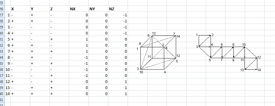
The main difference is that the first approach uses a full triangle strip for the whole cube. The normal of each vertex is the averaged normal of the triangle vertexes.
The second approach only uses 1 triangle strip for each face. This avoids vertex sharing, so each vertex can now have a normal that is not shared between faces. You then calculate the normals for each face (this is not hard, you already have a side, back and top vectors that you used to create the faces, now you just need to match them correctly with the faces). Using that face on the fragment shader you can then shade each face individually.
this link helped me to make a cube in a single strip http://www.sierracosworth.nl/gamedev/geom_cube_NOK2.jpg.